The MaxiSys Elite application allows you to establish a data link to the electronic control system of the test vehicle via the VCI device for vehicle diagnosis, service or programming. You can operate functional tests, retrieve vehicle diagnostic information such as trouble codes, event codes and live data, and perform ECU reprogramming, for various vehicle control systems, such as engine, transmission, ABS and more.
1.Diagnosis 一 a comprehensive section which includes all available functions: reading, clearing, saving and printing diagnostic information, as well as performing active tests and special functions
2.Service 一 a separate section designed to perform vehicle scheduled service and maintenance, such as to reset the service lights and perform calibration for various systems
3.Programming/Coding 一 a separate section designed for quick access to ECU reprogramming operations. After a section is selected and the tablet establishes communication with the vehicle via the VCI device, the corresponding function menu or selection menu displays.
Diagnosis
There are two options available when accessing the Diagnosis section:
1.Auto Scan 一 starts auto scanning for all the available systems on the vehicle
2.Control Units 一 displays a selection menu of all available control units of the test vehicle
Auto Scan
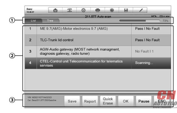
The Auto Scan function performs a comprehensive scanning over all the systems on the vehicle’s ECU in order to locate fault systems and retrieve DTCs. The sample operation interface of Auto Scan displays as below:
1.Navigation Bar
2.Main Section
3.Functional Buttons
Navigation Bar
1.List Tab — displays the scanned data in list format
2.Tree Tab — display the scanned data in system distribution diagram format
3.Progress Bar — indicates the test progress
Main Section
1.List Tab
Column 1 – displays the system numbers
Column 2 – displays the scanned systems
Column 3 – displays the diagnostic marks indicating different conditions of the test result:
-!-: Indicates that the scanned system may not support the code reading function, or there is a communication error between the tester and the control system.
-?-: Indicates that the vehicle control system has been detected, but the tester cannot accurately locate it.
Fault | #: Indicates there is/are detected fault code(s) present; “#” indicates the number of the detected faults.
Pass | No Fault: Indicates the system has passed the scanning process and no fault has been detected.
2.Tree Tab
The tree tab screen displays a system distribution diagram of the vehicle control modules. The scanned system which has passed scanning with no fault is shown in blue font; whereas the scanned system that has been detected with fault present is shown in red font.
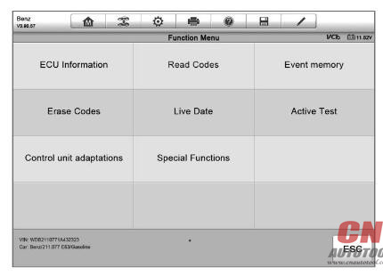
17.Tab the @ button to the right of the system item, on which you want to perform further diagnosis and other test activities. A Function Menu screen shall then display.
Functional Buttons
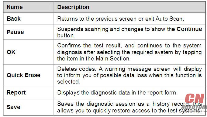
The table below provides a brief description of the Functional Buttons’operations in Auto Scan:
Control Units
This option allows you to manually locate a required control system for testing through a series of choices. You simply follow the menu driven procedure, and make proper selection each time; the program will guide you to the diagnostic function menu after a few choices you’ve made.
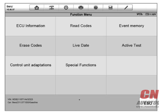
The Function Menu options vary slightly by different vehicles. The function menu may include:
1.ECU Information 一 provides the retrieved ECU information in detail. Selecting opens an information screen.
2.Read Codes 一 displays detailed information of DTC records retrieved from the vehicle control module.
3.Erase Codes 一 erases DTC records and other data from the ECM.
4.Live Data — retrieves and displays live data and parameters from the vehicle’s ECU.
5.Active Test 一 provides specific subsystem and component tests. This Auto Diagnostic tool may appear as Actuators, Actuator Test, or Function Tests, etc., and the tests options vary depending on the manufacturer and model.
6.Special Functions 一 provides component adaptation or variant coding functions for custom configurations, and also allows you to reprogram adaptive values for certain components after making repairs. Depending on the test vehicle, this selection may sometimes appear as Control Unit Adaptations, Variant Coding, Configuration or something similar.
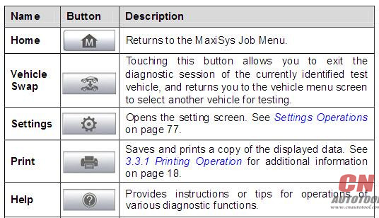
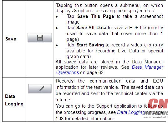
NOTE: With the diagnostic toolbar on top of the screen throughout the whole diagnostic procedures, you are allowed to make various controls of the diagnostic information at any time, such as printing and saving the displayed data, get help information, or perform data logging, etc.
To perform a diagnostic function
1.Establish communication with the test vehicle via the VCI device.
2.Identify the test vehicle by selecting from the menu options.
3.Select the Diagnosis section.
4.Locate the required system for testing by Auto Scan or through menu driven selections in Control Units.
5.Select the desired test from the Function Menu.
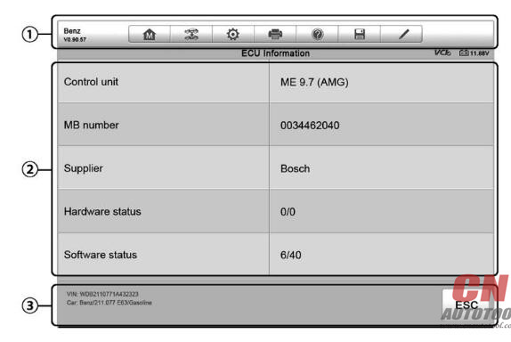
ECU Information
This function retrieves and displays the specific information for the tested control unit, including unit type, version numbers and other specifications. The Autel Scanner ECU Information screen displays as below:
Diagnostics Toolbar Buttons – for detailed descriptions of the operations for each button.
Main Section 一 the left column displays the item names; the right column shows the specifications or descriptions.
Functional Button 一 In this case, only a Back (or sometimes an ESC) button is available; tap it to exit after viewing.
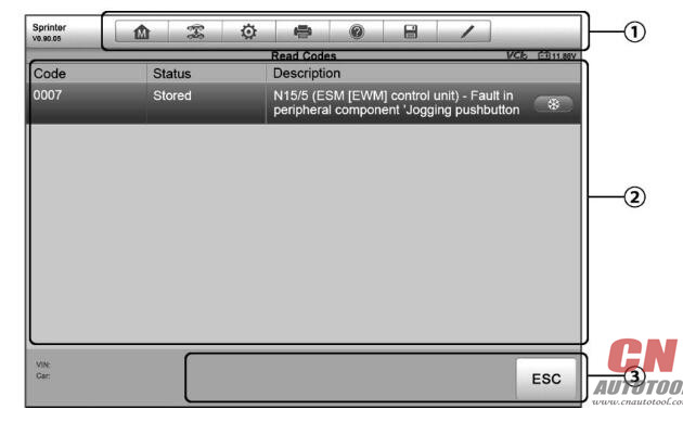
Read Codes
This function retrieves and displays the DTCs from the system. The Read Codes screen varies for each vehicle some vehicles, freeze frame data can also be retrieved sample Read Codes screen displays as below:
Diagnostics Tool bar Buttons – see Table 4-2 Diagnostics Toolbar Buttons on page 33 for detailed descriptions of the operations for each button.
Main Section
* Code Column – displays the retrieved codes from the vehicle.
* Status Column – indicates the status of the retrieved codes.
* Description Column 一 detailed descriptions for the retrieved codes.
* Snowflake Icon – only displays when freeze frame data is available for viewing; Selecting displays a data screen, which looks very similar to the Read Codes interface, therefore same operation method may be applied.
Functional Button – in this case, only a Back (or sometimes an ESC) button is available; tap it to return to the previous screen or exit the function.
Erase Codes
After reading the retrieved codes from the vehicle and certain repairs have been carried out, you can decide to erase the codes from the vehicle using this function. Before performing this function, make sure the vehicle’s ignition key is in the ON (RUN) position with the engine off.
To erase codes
1.Tap Erase Codes from the Function Menu.
2.A warning message displays to inform you of data loss when this function is applied.
1).Tap Yes to continue. A confirming screen displays when the operation is successfully done.
2).Tap No to exit.
3.Tap ESC on the confirming screen to exit Erase Codes.
4.Check the Read Codes function again to ensure the operation is successful.
A.Live Data
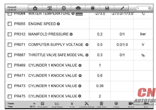
When this function is selected, the screen displays the data list for the selected module. The items available for any control module vary from one vehicle to another. The parameters display in the order that they are transmitted by the ECM, so expect variation between vehicles.
Gesture scrolling allows you to quickly move through the data list. Simply touch the screen and drag your finger up or down to reposition the parameters being displayed if the data covers more than one screen. The figure below shows a typical Live Data screen:
B.Active Test
The Active Test function is used to access vehicle-specific subsystem and component tests. Available test vary by manufacturer, year, and model, and only the available tests display in the menu.
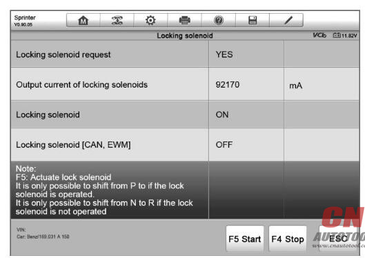
During an active test, the tester outputs commands to the ECU in order to drive the actuators. This test determines the integrity of the system or parts by reading the engine ECU data, or by monitoring the operation of the actuators, such as switching a solenoid, relay, or switch, between two operating states.
Selecting Active Test opens a menu of test options that varies by make and model. Selecting a menu option activates the test. Follow all screen instructions while performing tests. How and what information is presented on the screen varies according to the type of test being performed. Some toggle and variable control tests display Active Test Controls at the top of the screen with data stream information below, or vice versa.
The functional buttons at the lower right corner of the Active Test screen manipulate the test signals. The operational instructions are displayed on the main section of the test screen. Simply follow the on-screen instructions and make appropriate selections to complete the tests. Each time when an operation is successfully executed, message such as “Command Finished”, “Activation Successful”, or something similar displays. Tap the ESC functional button to exit the test when finished.

Leave a Reply